Whirlpool WMH73521CS User Manual
Browse online or download User Manual for Kitchen Whirlpool WMH73521CS. Whirlpool WMH73521CS User Manual
- Page / 2
- Table of contents
- BOOKMARKS
Rated. / 5. Based on customer reviews
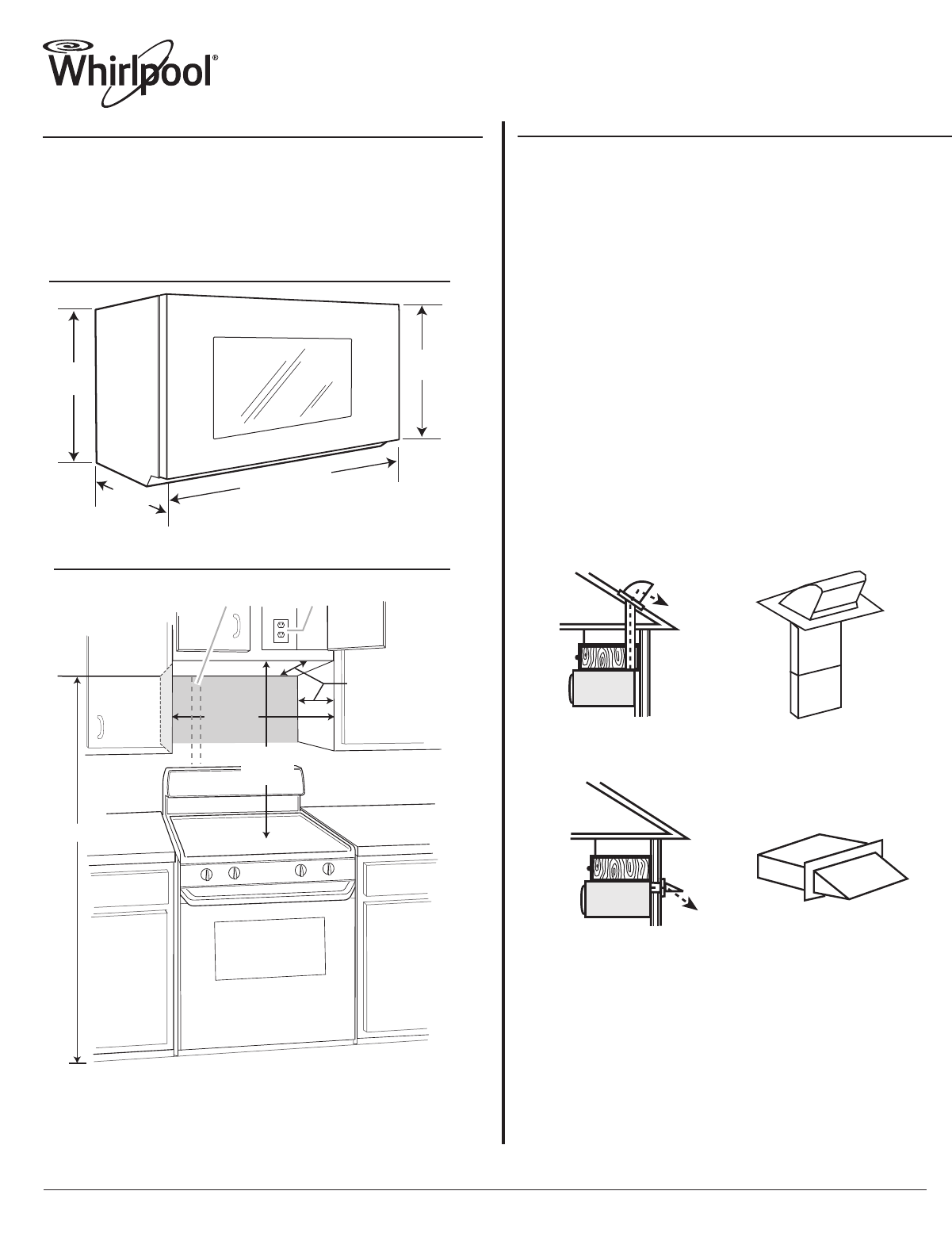
29
⁷⁄₈
" (76.0 cm)
1
6
¹⁄₄
"
(41
.3 cm)
1
7
¹⁄₈
"
(43
.5 c
m)
16
¹⁵⁄₁₆
"
(43.0 cm)
+/-
³⁄₈
"
(1.
0 cm)
PRODUCT MODEL NUMBER
PRODUCT DIMENSIONS
VENTING DESIGN SPECIFICATIONS
Electrical: A 120-Volt, 60-Hz, AC-only, 15- or 20-amp electrical supply with
a fuse or circuit breaker. A time-delay fuse or time-delay circuit breaker is
recommended. It is recommended that a separate circuit serving only this
microwave oven be provided.
Microwave Hood Combination
Because Whirlpool Corporation policy includes a continuous commitment to improve
our products, we reserve the right to change materials and specifications without notice.
Dimensions are for planning purposes only. For complete details, see Installation
Instructions packed with product. Specifications subject to change without notice.
Ref. W10652354A
1/16/14
CABINET OPENING DIMENSIONS
12" (30.5 cm) min.
14" (35.6 cm) max.
30"
(76.2 cm)
min.
A B
upper cabinet and
side cabinet depth
30"
(76.2 cm)
typical*
A. 2" x 4" wall stud
B. Grounded 3-prong outlet
66" (167.6 cm) min.
The grounded 3-prong outlet must be inside the upper cabinet.
*30" (76.2 cm) is typical for 66" (167.6 cm) installation height.
Exact dimensions may vary depending on type of range/cooktop below.
WMH73521C WMH76719C
This section is intended for architectural designer and builder/contractor
reference only.
NOTES:
●
Vent materials needed for installation are not provided with microwave hood
combination.
●
We do not recommend using a flexible metal vent.
●
To avoid possible product damage, be sure to vent air outside, unless using
recirculation installation. Do not vent exhaust air into concealed spaces, such
as spaces within walls or ceilings, attics, crawl spaces or garages.
For optimal venting installation, we recommend:
●
using roof or wall caps that have back draft dampers
●
using a rigid metal vent
●
using the most direct route by minimizing the length of the vent and number of
elbows to provide efficient performance
●
using uniformly sized vents
●
using duct tape to seal all joints in the vent system
●
using caulking compound to seal exterior wall or roof opening around cap
●
not installing 2 elbows together, for optimal hood performance
If venting through the wall, be sure that there is proper clearance within the wall
for the damper to open fully.
If venting through the roof, and rectangular to round transition is used, be sure
there is at least 3" (7.6 cm) of clearance between the top of the microwave oven
and the transition piece.
Roof venting Roof cap
Wall venting Wall cap
Page 1 of 2
1
2
Summary of Contents
Page 1 - Microwave Hood Combination
29⁷⁄₈" (76.0 cm)16¹⁄₄"(41.3 cm)17¹⁄₈"(43.5 cm)16¹⁵⁄₁₆"(43.0 cm)+/-³⁄₈"(1.0 cm)PRODUCT MODEL NUMBERPRODUCT DIMENSIONSVENTING D
Page 2 - Recommended Standard Fittings
6" (15.2 cm) vent system = 73 ft (22.2 m) totalA BCD6 ft (1.8 m)2 ft(0.6 m)A. Tw
More documents for Kitchen Whirlpool WMH73521CS

Whirlpool WMH73521CS User Manual
(13 pages)

Whirlpool WMH73521CS User Manual
(13 pages)

Whirlpool WMH73521CS User Manual
(2 pages)

Whirlpool WMH73521CS User Manual
(8 pages)
Related products and manuals for Kitchen Whirlpool WMH73521CS
Kitchen Whirlpool GXU7130DXS User Manual
 (2 pages)
(2 pages)
Kitchen Whirlpool GXW6530DXS User Manual
(3 pages)
(3 pages)
Kitchen Whirlpool UXT4130ADS User Manual
(3 pages)
(3 pages)
Kitchen Whirlpool UXT5530AAS User Manual
(3 pages)
(3 pages)
Kitchen Whirlpool UXD8636DYS User Manual
(3 pages)
(3 pages)
Kitchen Whirlpool UXT3030ADW User Manual
(2 pages)
(2 pages)
Kitchen Whirlpool UXT2030ADW User Manual
 (28 pages)
(28 pages)
Kitchen Whirlpool RBD245PRS User Manual
(28 pages)
(28 pages)
Kitchen Whirlpool GC5000XE User Manual
(2 pages)
(2 pages)
Kitchen Whirlpool WOC54EC0AS User Manual
(40 pages)
(40 pages)
Kitchen Whirlpool WMH53520CS User Manual
 (8 pages)
(8 pages)
Kitchen Whirlpool GXW7330DXS User Manual
(3 pages)
(3 pages)
Kitchen Whirlpool WOS92EC7AS User Manual
(10 pages)
(10 pages)
Kitchen Whirlpool WMH31017AS User Manual
(13 pages)
(13 pages)
Kitchen Whirlpool WMC10007AW User Manual
(15 pages)
(15 pages)
Kitchen Whirlpool GXW7230DAS User Manual
(3 pages)
(3 pages)
Kitchen Whirlpool GC2000PE User Manual
(2 pages)
(2 pages)
Kitchen Whirlpool UXT4030ADS User Manual
(3 pages)
(3 pages)
Kitchen Whirlpool UMC5225DS User Manual
(17 pages)
(17 pages)
Kitchen Whirlpool WGG755S0BE00 User Manual
(16 pages)
(16 pages)
© 2020, manymanuals.com. All rights reserved. | 1.599 s |
 Manymanuals.com
 Manymanuals.de
 Manymanuals.fr
 Manymanuals.it
 Manymanuals.pl
 Manymanuals.cz
 Manymanuals.es
 Manymanuals-pt.com
Comments to this Manuals