W10301482B .ON TRAPYLNO ESU S’NAICINHCET ECIVRES ROF
TECH SHEET - DO NOT DISCARD PAGE 4
TEST #2 Machine Control Power Check
This test is used to determine if power is present at
the machine control electronics.
NOTE: The drum light is controlled by the machine
control on all models.
1. Plug in dryer or reconnect power.
2. Open the door.
➔
If the drum light illuminates, then power is
present at the machine control. Go to
TEST #6, page 8.
➔ If the drum light fails to illuminate, do not
assume the machine control electronics needs
replacement. Several conditions may cause
the drum light not to illuminate, including a bad
bulb. If the drum light does not illuminate, go
to TEST #1, at left.
TEST #3 Drive Motor Circuit
This test will check the wiring to the motor and the
motor itself. The following items are part of this
motor system:
– Harness/
connection
– Thermal fuse
– Belt/belt switch
– Drive motor
– Centrifugal switch
– Door switch
– Machine control
electronics. See ESD
information, page 1.
1. Unplug dryer or disconnect power.
2. Access the machine control electronics and
measure the resistance across P8-4 and P9-1.
See Accessing & Removing the Electronic
Assemblies, page 9.
➔ If resistance across P8-4 and P9-1 is in the
range of 1 to 6 Ω, replace the machine control
electronics.
➔ Otherwise, go to step 3.
3. Check the wiring and components in the path
between these measurement points by referring
to the appropriate wiring diagram. See pages 11
and 12.
4. Perform TEST #4b, page 7. If thermal fuse is OK,
continue with step 5.
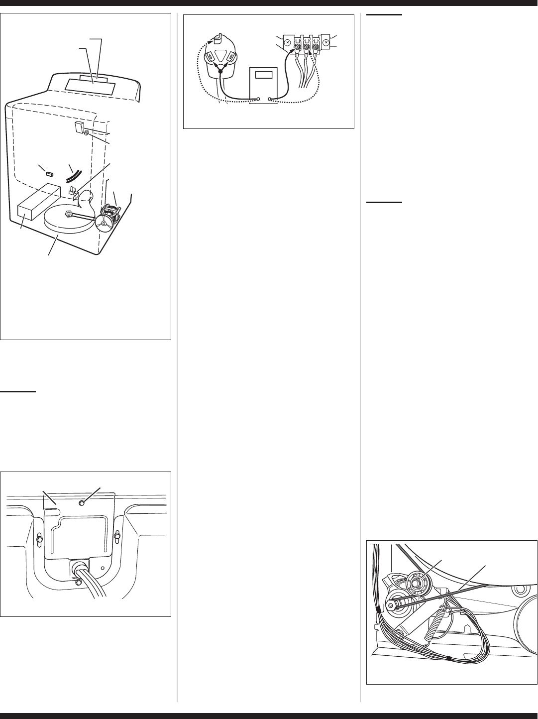
5. Check the belt switch and drive motor. Access the
belt switch and drive motor by removing the back
panel. See Removing the Back Panel, page 10.
Slowly remove the drum belt from the
spring-loaded belt switch tension pulley, gently
letting the pulley down. See figure 5.
Door
Switch
See Removing the Front Panel/Drum Assembly,
page 9, to access:
■
■
■
■
Exhaust
Moisture Sensors
Thermistor
Thermal Cut-off
Inlet Thermistor/
High Limit Thermostat
Heater
Assembly
See Accessing & Removing the Electronic Assemblies,
page 9, to access:
■
■
Machine Control Electronics
User Interface Assembly
Moisture
Sensor
Strips
■
■
Heater
Thermal Fuse
Assembly
See Removing the
Back Panel, page 10,
to access:
■
■
■
■
■
Drum Light Assy.
Water Nozzle
(Steam Model)
Water Valve Assy.
(Steam Model)
Drive Motor
Belt Switch
Figure 2. Component locations.
TROUBLESHOOTING TESTS
NOTE: These checks are done with the dryer
unplugged or disconnected from power.
TEST #1 Supply Connections
This test should only be done after confirming proper
voltage at the outlet.
1. Unplug dryer or disconnect power.
2. Remove the cover plate from the back of the
dryer. See figure 3.
3. Make sure the power cord is securely fastened
to the terminal block.
4. With an ohmmeter, check for continuity between
the neutral (N) terminal of the plug and the center
contact on the terminal block. See figure 4.
➔ If there is no continuity, replace the power cord
and test the dryer.
➔ If there is continuity, go to step 5.
5. In a similar way, check which terminal of the plug
is connected to the left-most contact on the
terminal block and make a note of it. This will be
L1 (black wire) in the wiring diagram. See figure 4
above and the appropriate wiring diagram. See
pages 11 and 12.
➔ When this is found, go to step 6.
➔ If neither of the plug terminals have continuity
with the left-most contact of the terminal
block, replace the power cord and test the
dryer.
6. Access the machine control electronics without
disconnecting any wiring to the control board.
See Accessing & Removing the Electronic
Assemblies, page 9.
7. With an ohmmeter, check for continuity between
the L1 terminal of the plug (found in step 5) and
P9-2 (black wire) on the machine control board.
See figure 16, page 9.
➔ If there is continuity, go to step 8.
➔ If there is no continuity, check that wires to the
terminal block are mechanically secure. If so,
replace the main wire harness and test the dryer.
8. Check for continuity between the neutral (N)
terminal of the plug and P8-3 (white wire) on the
machine control board.
➔ If there is continuity, go to step 9.
➔ If there is no continuity and the mechanical
connections of the wire are secure, replace the
main wire harness.
9. Visually check that the P5 connector is inserted
all the way into the machine control electronics.
10. Visually check that the user interface assembly
is properly inserted into the front console.
11. If both visual checks pass, replace the user
interface assembly.
13. Plug in dryer or reconnect power.
14. Perform the Console Buttons and Indicators
Diagnostic test, page 1, to verify repair.
15. If indicators still do not light, the machine control
electronics has failed:
➔ Unplug dryer or disconnect power.
➔
Replace the machine control electronics.
➔
Plug in dryer or reconnect power.
➔
Perform the Console Buttons and Indicators
Diagnostic test, page 1 to verify repair.
Remove Screw
Cover
Plate
Figure 3. Remove the cover plate.
COM
N
L1
Power Cord
Plug
Terminal Block
Figure 4. Plug-to-terminal connections.
Drum
Belt
Tension
Pulley
Figure 5. Slowly remove drum belt.
12. Replace all parts and panels.
➔
Replace all parts and panels.

 (28 pages)
 (16 pages)
 Manymanuals.com
 Manymanuals.de
 Manymanuals.fr
 Manymanuals.it
 Manymanuals.pl
 Manymanuals.cz
 Manymanuals.es
 Manymanuals-pt.com
Comments to this Manuals