Whirlpool DryAire LMA1053L Specifications
Browse online or download Specifications for Electric laundry dryers Whirlpool DryAire LMA1053L. Whirlpool DryAire LMA1053L Specifications User Manual
- Page / 41
- Table of contents
- BOOKMARKS
- DEHUMIDIFIER 1
- INSTALLATION & OPERATION 1
- LIMITED WARRANTY 2
- 1.0 Installation 5
- FIELD FABRICATED 6
- SUPPORT BASE METHOD 6
- CEILING SUSPENDED 8
- INSTALLATION 8
- 1.7. Condensate Drain Piping 11
- 2.0. Air Distribution 12
- Figure 2.1.2. Duct Layout 13
- Figure 2.1.3. Duct Layout 14
- OUTDOOR (MAKE-UP) AIR 15
- COMMERCIAL APPLICATION ONLY 15
- 3.0. Outdoor Remote Condenser 17
- OC-SERIES OUTDOOR 18
- REMOTE CONDENSERS 18
- ELECTRICAL DATA 20
- CONTROL WIRING DIAGRAM #1 23
- IMPOR T ANT 24
- 6.0. Start-Up Procedure 27
- 7.0. Operational Sequence 27
- REFRIGERATION FLOW DIAGRAM 28
- DEHUMIDIFIER ONLY [Fig. 1] 28
- REMOTE OUTDOOR 28
- AIR-COOLED CONDENSER 28
- SYSTEM DESIGN 28
- 7.2. Power On ! 29
- 9.0. Maintenance Procedure 30
- DEHUMIDIFIER RUNS 33
- 11.2. Dehumidifier Off 34
- Not Recommended! 36
- Recommended! 36
- 15.0. Compressor Failure 37
- MUST BE WEIGHED INTO SYSTEM 39
- Start-up Report 40
Summary of Contents
DEHUMIDIFIERINSTALLATION & OPERATIONMANUALFor Models: DRY-10-SERIESDRY-20-SERIESDRY-25-SERIESDRY-30-SERIESDRY-40-SERIESDRY-50-SERIESOC-10-SERIE
1.6.2. Controller LocationStandard low voltage (24 volt) AC wiring, such as that used with standard air conditioning equipment, is required for the 24
DryAire Systems
1.8. Pool Water EvaporationThe air velocity directly above and close to the pool water surface must be kept below(10) ft. per / minute. Higher air vel
DryAire Systems
2.1. Ducted Air SystemsIf the ductwork is installed in an unconditioned area, then sufficient insulation should be usedto prevent condensation and hea
DryAire Systems
2.5. Auxiliary Heat (Duct Heater), If RequiredIn certain climates or regions and with some pool enclosures, construction materials,additional suppleme
DryAire Systems
OUTDOOR LINE SIZE REQUIRED (NOT TO EXCEED 50 FT.)CONDENSER OC-10 OC-20 OC-25 OC-30 OC-35 OC-40
DryAire Systems
Only trained, qualified service technicians should attempt instal-lation, or repair of DryAire dehumidification equipment. Danger of high voltagecompo
ELECTRICAL DATAAll specifications, descriptions, rating and productsherein are subject to change without notice orrecourse.Compressor FL
DryAire Systems
208/230V 208/230V 460V1 PH 3 PH 3 PHDRY-10-VSERIESELECTRICAL DATA208/230V 208/230V 460V1 PH 3 PH 3 P
DryAire Systems
23 DryAire System
4.0. Head Pressure Controller / Remote CondenserThe capacity of an air cooled condenser will vary with the difference between the entering air dry bul
MOTOR HP RPM MOTOR(ESP) (ESP) PULLEYMODEL NO. CFM 0.5" 1.0" 0.5" 1.0" 0.5" 1.0"DRY-10
6.0. Start-Up ProcedureA complete start-up will minimize problems and expensive callbacks. The start-up will be quickerand easier if the space to be d
REFRIGERATION FLOW DIAGRAM27
7.1. System Modes of Operation7.1.1. Dehumidification / Air Reheat ModeWhen the room air requires dehumidification and heating, the dehumidifier runsi
TABLE OF CONTENTS PAGE1.0. Installation...41
Thermostat Set-Points7.2.3. The Honeywell® automatic change-over t-stat has a minimum 3°F dead band. Setpoint require 2°F for heat and 2°F for cool. F
9.2. Six Month InspectionWITH POWER SUPPLY OFF!1. Check the blower belts in the dehumidifier and the optional remote outdoorcondenser for excessive we
10.3. Evaporator Coil Freeze UpEntering air temperature too low. Raise entering air temperature.Insufficient evaporator air flow. Check system air flo
11.0. Service Diagnosis Chart11.1. Dehumidifier RunsDEHUMIDIFIER RUNSLOW HEAD HIGH HEAD LOW SUCTIONHIGH SUCTION
11.2. Dehumidifier OffDEHUMIDIFIER OFF{CONTACTOR CLOSED}COMPRESSOR HUMS DOES NOT HUM• Refrigerant pressure not
12.0. Unit Operating Guidelines12.1. Controller Set-PointsIt is important to determine your comfortable set points and to avoid further controlleradju
Not Recommended!2.5W or MoreIntake30° or MoreDischarge20° or LessDischargeTurnVanesW5W or More ForStatic Pressure RegainIntakeTurnVanesWDryAireDryAire
14.0. Outside Air Pre-Heating RequirementsDryAire Systems require that outside air be pre-heated if mixed air temperatures inside thedehumidifier migh
YOU MUST CLEAN THE SYSTEM THOROUGHLY TO PREVENT REPEATED COMPRESSOR BURNOUTS!15.1. Mild Burnouts (use new R-22)If the burnout is mild, recover the ref
DryAire FactoryModel No. ChargeR-22DRY-10 SERIES 11#DRY-20 SERIES 12# DRY-25 SERIES 17# DRY-30 SERIES 19# DRY-40 SERIE
TABLE OF CONTENTS PAGE3.3. Control Wiring Diagram #1...223.4. Control Wiring Dia
Start-up Report DRY-SERIES Dehumidification Systems EquipmentIn order for warranty to be valid, a start-up report must be completed and returned to th
W185 N11497 WHITNEY DRIVE GERMANTOWN, WI 53022(262) 250-8500 FAX (262) 250-0886 eMAIL [email protected]
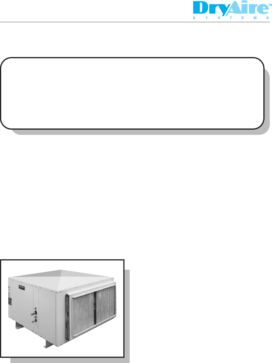
1.0 Installation1.1. Product OverviewThe DryAire dehumidifier is a very high capacity, self contained dehumidifier that is manufactured by qualified
1.3. Unpacking and InspectionDryAire performs several physical inspections and multiple tests on each dehumidifier duringand after the various product
DryAire Systems
Do not install a standard dehumidifier in an unconditioned space or where ambient temperatures can fall below 45°F.If you must install the dehumidifie
DryAire Systems
More documents for Electric laundry dryers Whirlpool DryAire LMA1053L

Related products and manuals for Electric laundry dryers Whirlpool DryAire LMA1053L
 (16 pages)
 (16 pages)
 (11 pages)
 (64 pages)
 (56 pages)
 (32 pages)
© 2020, manymanuals.com. All rights reserved. | 0.575 s |
 Manymanuals.com
 Manymanuals.de
 Manymanuals.fr
 Manymanuals.it
 Manymanuals.pl
 Manymanuals.cz
 Manymanuals.es
 Manymanuals-pt.com
Comments to this Manuals